

Modern vehicles rely on a network of sensors to manage engine performance, and a critical component in this system is the Accelerator Pedal Sensor (APS). This sensor translates the physical movement of your gas pedal into an electrical signal that tells the engine’s computer how much power to deliver. When this sensor fails, you might experience issues like poor acceleration, rough idling, or even your car entering “limp mode.”
Before you rush to a mechanic for an expensive replacement, you can often diagnose the problem yourself. Learning how to test accelerator pedal sensor with multimeter is a straightforward diagnostic procedure that can save you time and money. This guide will provide a clear, step-by-step process for any car owner with basic tools, helping you determine if the sensor is truly the source of your vehicle’s issues.
Why Knowing How to Test Your Accelerator Pedal Sensor Matters
A faulty accelerator pedal sensor can mimic a wide range of other, more serious engine or transmission problems, potentially leading to incorrect and costly repairs. By learning how to perform this simple diagnostic test yourself, you can accurately pinpoint the issue and avoid unnecessary expenses. This skill empowers you to take control of your vehicle’s maintenance, ensuring you only replace parts that are genuinely failing. It provides peace of mind and builds confidence in your ability to handle basic automotive diagnostics, saving you from a costly trip to the mechanic for what could be a simple fix.
8 Step-by-Step Guide: How to Test Accelerator Pedal Sensor with Multimeter
Step 1: Locate the Accelerator Pedal Sensor (APS)
Before you can begin any diagnostic testing, you need to find the sensor itself. In most modern vehicles, the Accelerator Pedal Sensor is integrated directly into the accelerator pedal assembly.
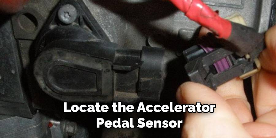
You will find it mounted to the firewall in the driver’s side footwell. It’s a “drive-by-wire” system, meaning there is no physical throttle cable connecting the pedal to the engine. Instead, a wiring harness with several wires will be connected to the top of the pedal assembly. Carefully inspect the area to identify the sensor and its electrical connector, as this is where you will be performing your tests.
Step 2: Gather Your Tools and Safety Equipment
For this job, you will need a digital multimeter capable of measuring DC voltage, a set of back-probe pins or T-pins to safely access the wiring, and your vehicle’s service manual or a reliable online wiring diagram. Safety is paramount, so wear safety glasses and gloves. Ensure your vehicle is parked on a level surface with the parking brake engaged and the wheels chocked. You will be working with the vehicle’s electrical system, so it is crucial to follow all safety precautions to prevent injury or damage to the car’s electronics.
Step 3: Identify the Correct Wires Using a Wiring Diagram
This is a critical step that requires precision. The accelerator pedal sensor typically has six wires arranged in two separate circuits for redundancy (APP1 and APP2). Each circuit has a power wire (usually 5 volts), a ground wire, and a signal wire. You must consult your vehicle’s specific wiring diagram to identify which wire corresponds to which function. Guessing can lead to short circuits and damage to the Engine Control Module (ECM). The diagram will show you the color and pin location for each wire, allowing you to accurately probe the correct signal wire for your voltage readings.
Step 4: Set Up Your Multimeter and Back-Probe the Connector
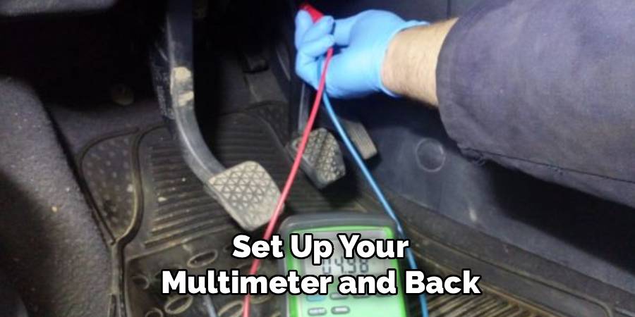
Set your digital multimeter to the DC voltage setting, typically denoted by “V” with a straight line. To get accurate voltage readings without damaging the connector, you will use back-probes. Gently insert a T-pin or back-probe pin alongside the signal wire you identified in the previous step, pushing it into the back of the electrical connector until it makes contact with the metal pin inside. Attach the red (positive) lead of your multimeter to this pin. Connect the black (negative) lead of your multimeter to a known good ground on the vehicle’s chassis, such as a bare metal bolt.
Step 5: Take the Initial Voltage Reading with the Pedal at Rest
With the multimeter properly connected, turn the vehicle’s ignition to the “ON” position without starting the engine. The engine must be off for this test. With the accelerator pedal completely untouched (at its resting or idle position), observe the voltage reading on your multimeter. This is your baseline voltage. Typically, this reading should be a low value, often around 0.5 to 0.7 volts. Refer to your service manual for the exact specification for your vehicle. A reading that is too high, too low, or zero at this stage indicates a potential problem with the sensor’s calibration or wiring.
Step 6: Test the Voltage Sweep Through the Pedal’s Range of Motion
This is the core of how to test accelerator pedal sensor with multimeter. While watching the multimeter’s display, slowly and smoothly press the accelerator pedal all the way to the floor. As you press the pedal, the voltage should increase in a smooth, linear fashion. There should be no sudden jumps, drops, or dead spots in the reading. At wide-open throttle (pedal fully depressed), the voltage should reach its maximum value, typically between 4.5 and 5.0 volts. A glitchy or erratic reading during this sweep is a clear sign that the sensor is faulty and needs replacement.
Step 7: Repeat the Test for the Second Sensor Circuit
For safety and redundancy, the APS has two independent sensors (APP1 and APP2). You must repeat the entire testing process for the second sensor circuit. Locate the signal wire for the second circuit using your wiring diagram and move your back-probe to that wire.
Perform the same test, taking a voltage reading at idle and then observing the sweep as you press the pedal to the floor. The second sensor often operates in reverse or at half the voltage of the first one. For example, it might read high at idle and sweep low, or it might sweep from 0.25 to 2.5 volts. Consult your manual and confirm the voltage sweeps smoothly.
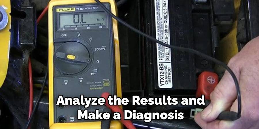
Step 8: Analyze the Results and Make a Diagnosis
After testing both circuits, analyze your findings. A healthy accelerator pedal sensor will show two separate, smooth voltage sweeps that correspond directly to the pedal’s movement and match the specifications in your service manual. If you observed any “dead spots,” erratic jumps, or voltage readings that were out of specification on either circuit, the sensor is faulty.
The presence of a smooth sweep confirms that the sensor itself is likely good, and any throttle response issues may stem from other components. This is the final step in learning how to test accelerator pedal sensor with multimeter and making a confident diagnosis.
Frequently Asked Questions (FAQs)
What Are the Symptoms of a Failing Accelerator Pedal Sensor?
Common symptoms of a bad APS include:
- Poor or hesitant acceleration
- The engine failing to respond to the gas pedal
- The vehicle being stuck in “limp mode” (reduced power)
- Rough or inconsistent idling
- The check engine light illuminating on the dashboard
These symptoms can be intermittent at first but will typically worsen over time as the sensor degrades further.
Can I Drive My Car with a Bad Accelerator Pedal Sensor?
While it may be technically possible to drive for a short distance, it is not recommended. A failing APS can cause unpredictable throttle response, making the vehicle unsafe to operate, especially in traffic. If the car enters limp mode, your speed will be severely limited. For your safety and the safety of others, you should have the vehicle inspected and repaired as soon as possible if you suspect the sensor is failing.
What Voltage Should I See When Testing the Sensor?
The exact voltage will vary by vehicle manufacturer, which is why a service manual is essential. However, a common pattern for the primary sensor (APP1) is a reading of approximately 0.5V at idle (pedal up) and a smooth sweep up to about 4.5V at wide-open throttle (pedal down). The secondary sensor (APP2) often works in reverse or at half the voltage of the primary one. The most important factor is a smooth, consistent change in voltage, not just the specific numbers.
Is It Necessary to Test Both Sensor Circuits?
Yes, it is absolutely necessary. The vehicle’s computer constantly compares the readings from the two sensor circuits as a safety check. A fault in just one of the circuits is enough to trigger a check engine light and cause performance issues. Testing both ensures you have a complete and accurate diagnosis. A problem might only exist in one of the two internal sensors, and skipping the second test could lead you to miss the fault.
What Is the Difference Between an APS and a TPS?
The Accelerator Pedal Sensor (APS) is located on the gas pedal assembly and reads the driver’s input. It sends this signal to the car’s computer. The Throttle Position Sensor (TPS) is located on the throttle body of the engine. The computer takes the signal from the APS and then tells the throttle body how much to open, and the TPS reports the throttle plate’s actual position back to the computer. In drive-by-wire systems, they work together to control engine speed.
Conclusion
Mastering how to test accelerator pedal sensor with multimeter is a valuable diagnostic skill that empowers you to accurately identify a common cause of engine performance issues. This process, while detailed, is well within the reach of a determined DIYer and can prevent the unnecessary cost and hassle of replacing the wrong parts. By methodically checking the voltage readings of both sensor circuits, you can make a confident diagnosis right in your own garage.
Don’t let a check engine light intimidate you. With a multimeter and a little patience, you have the ability to troubleshoot your vehicle’s electronics effectively. Taking the time to perform this test builds your skills, saves you money, and gives you the satisfaction of solving a problem yourself.