

Testing ABS sensors is crucial for ensuring the optimal performance and safety of a vehicle’s Anti-lock Braking System (ABS). These sensors play a pivotal role in preventing wheel lockup during intense braking situations, thereby maintaining vehicle control and reducing stopping distances. Regular testing helps detect potential malfunctions early, avoiding more significant issues down the line.
ABS sensors, located at each wheel, continuously monitor the wheels’ rotational speed and send this data to the ABS control unit. The system then uses this information to adjust the braking pressure on each wheel, preventing them from locking up and skidding, especially on slippery surfaces.
Symptoms of failing ABS sensors include the flashing warning light on the dashboard, brakes locking up under hard braking conditions, and unexpected ABS activation at low speeds. These signs indicate it might be time to learn how to test a ABS sensor to promptly diagnose and address any issues.
Understanding ABS Sensor Components
A. Explaining the Role of ABS Sensors in Vehicle Safety Systems
ABS sensors are integral to the vehicle’s safety mechanisms, specifically within the Anti-lock Braking System. Their primary role is to monitor the speed of each wheel and communicate this data to the ABS control unit.
This continuous monitoring allows the system to adjust the braking force applied to each wheel, ensuring stability and steerability during abrupt stops. By preventing wheel lockup, ABS sensors significantly reduce the risk of skidding and enable the driver to maintain control over the vehicle in various driving conditions.
B. Identifying the Location of ABS Sensors on the Vehicle
Typically, ABS sensors are positioned near the wheel bearings of each wheel. This strategic placement allows them to accurately measure the wheel speed by detecting the rotating parts of the wheel hub or axle.
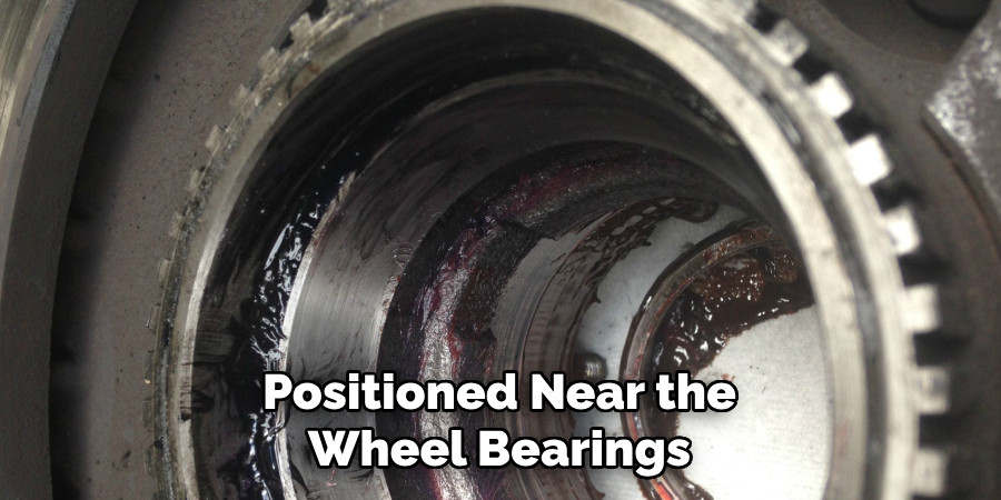
Depending on the vehicle’s design, ABS sensors can be found either in the wheel hub assembly or attached to the brake backing plate. Vehicle owners must familiarize themselves with their specific vehicle layout to efficiently locate and inspect these sensors when needed.
C. Learning about ABS Sensor Wiring and Connectors
ABS sensor wiring and connectors are critical components that ensure the sensors can transmit data to the ABS control unit effectively. Each sensor is connected to the vehicle’s electrical system through a wiring harness comprising at least two wires encased in protective insulation.
The connectors, typically made of durable plastic with metal terminals, provide a secure connection between the sensor and the wiring harness. Over time, these connectors and wires can suffer from wear, corrosion, or damage, which may interfere with the sensor’s ability to transmit data, underscoring the importance of regular inspection and maintenance.
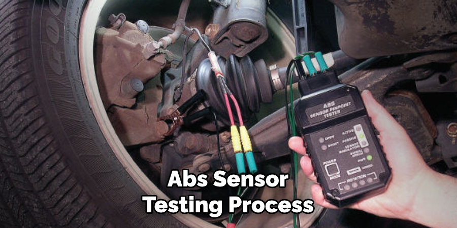
Preparing for Testing
Before commencing with the ABS sensor testing process, it’s essential to ensure that both the vehicle and the testing environment are adequately prepared to guarantee the safety and accuracy of the test results. This preparation involves several key steps:
A. Ensuring Vehicle Safety and Stability
Prioritize safety by parking the vehicle on a level and stable surface to prevent any unintended movement during testing. This stable foundation is crucial for conducting accurate tests and ensuring personal safety. Engage the parking brake to further secure the vehicle. Place wheel chocks around the tires that are not being lifted to add an extra layer of stability and safety.
B. Gathering Necessary Tools
Collect all the tools and equipment required to test the ABS sensor. Essential tools include a hydraulic jack and jack stands to safely lift and support the vehicle, allowing access to the ABS sensors located near the wheels. A digital multimeter is critical for testing the electrical continuity and voltage output of the ABS sensors. It’s also advisable to have gloves and protective eyewear for personal safety during the process.
C. Reviewing Vehicle Service Manual for Specific Testing Procedures
Each vehicle may have specific requirements or warnings when it comes to testing the ABS sensors. Consult the vehicle’s service manual for detailed instructions and safety warnings specific to your model.

The manual will provide valuable insights into the ABS system, including sensor locations, recommended testing procedures, and safety precautions. This step is vital for ensuring that the testing is conducted correctly and safely, according to the manufacturer’s specifications.
Accessing ABS Sensors
A. Locating ABS Sensors on Each Wheel Hub
The first crucial step in testing ABS sensors involves accurately locating the sensors on each wheel hub. As previously noted, ABS sensors are typically positioned near the wheel bearings or the wheel hub assembly.
To find them, start by safely elevating the vehicle using a hydraulic jack and securely placing it on jack stands. Remove the wheel to expose the brake assembly and the wheel hub, where the ABS sensor is mounted. Look for a small, cylindrical component attached to a wiring harness, which is the hallmark appearance of an ABS sensor.
B. Clearing Away Any Debris or Obstructions Around Sensors
Once the ABS sensors are located, it’s essential to ensure that the area around them is clean and free of any debris or obstructions. Road grime, dirt, and other contaminants can accumulate around the sensors, potentially interfering with their ability to accurately measure wheel speed.
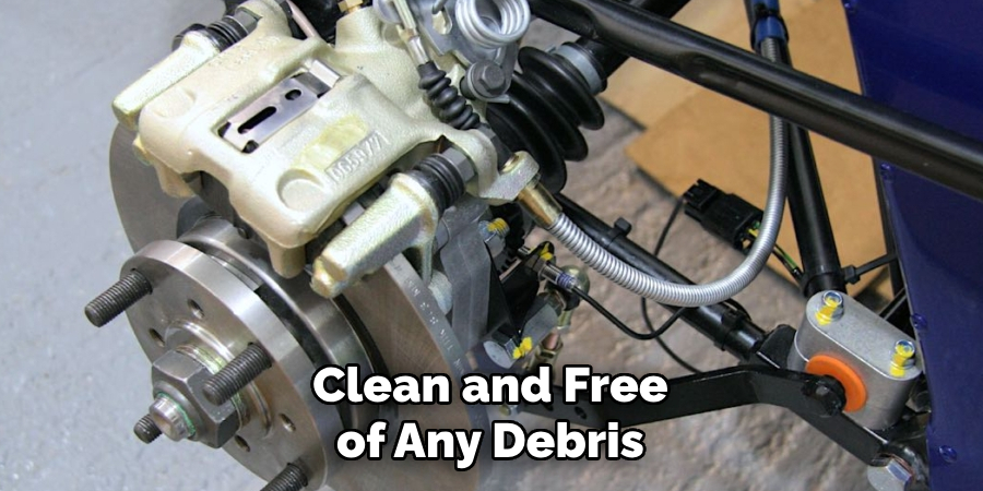
Use a soft brush or compressed air to gently clean the area around the sensors. Be cautious not to apply excessive force that might damage the sensor or its wiring.
C. Ensuring Safe Access to Sensors for Testing
Safety is paramount when accessing ABS sensors for testing. Always ensure that the vehicle is securely supported on jack stands and that the area is clear of any tools or obstructions that might pose a tripping hazard.
Wear gloves and safety glasses to protect yourself from sharp edges and potential contaminants. Double-check the vehicle’s stability before proceeding with the testing process to prevent any accidents or injuries.
How to Test a ABS Sensor: Testing ABS Sensor Wiring and Connectors
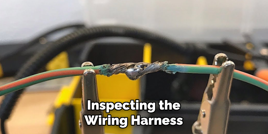
A. Inspecting Wiring Harness for Damage or Wear
Begin the inspection of the ABS sensor wiring harness by visually examining its entire length for any signs of wear, damage, or degradation. Look specifically for areas where the insulation may be cracked, frayed, or missing, which could expose the wires within. This exposure can lead to short circuits or open circuits, impairing the sensor’s functionality.
It is also important to check for any signs of melting or burn marks, which could indicate overheating issues. Flex the wiring harness gently along its length to uncover any hidden damage. If any wear or damage is discovered, the wiring harness should be replaced to ensure the proper functioning of the ABS system.
B. Checking Connector for Corrosion or Loose Connections
After inspecting the wiring harness, the next step involves examining the ABS sensor connector. Disconnect the connector carefully to inspect both the male and female components for signs of corrosion, dirt, or moisture. These elements can cause poor electrical conductivity and interfere with the sensor’s performance.
Also, check for damaged or bent pins that could hinder a secure connection. Ensure the connector fits snugly and securely when reattached, as loose connections can result in intermittent signal transmission issues. Cleaning the connectors with an appropriate electrical contact cleaner can often restore connectivity if corrosion or dirt is present.
C. Performing Continuity Test with Multimeter
Finally, a continuity test should be performed using a digital multimeter to thoroughly assess the integrity of the ABS sensor wiring and connectors. This test will help to identify any electrical breaks or short circuits within the wiring harness.
Set the multimeter to the continuity setting, typically displaying a symbol resembling a soundwave. Connect one probe of the multimeter to one end of the wiring harness and the other probe to the opposite end.
A continuous beep or a reading close to zero ohms indicates that the wiring harness has good electrical continuity. Repeat this process for each wire within the harness. If the multimeter does not beep or shows a reading much higher than zero, this signifies a break in the circuit, and the wiring harness will need to be replaced to ensure the ABS system functions correctly.
How to Test a ABS Sensor: Testing ABS Sensor Signal
A. Disconnecting ABS Sensor Connector
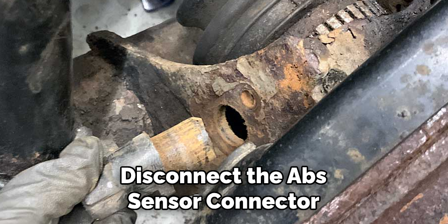
To initiate the testing of the ABS sensor signal, the first step is to disconnect the ABS sensor connector. This is typically a simple plug that can be carefully disengaged, often secured with a locking tab or clip. Exercise caution to avoid damaging the connector or wiring.
This disconnection is crucial for testing because it isolates the sensor, allowing for accurate measurement of its signal output without interference from the vehicle’s electrical system.
B. Setting Multimeter to AC Voltage Mode
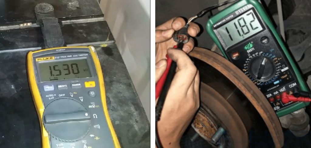
After disconnecting the ABS sensor, prepare a digital multimeter by setting it to AC voltage mode. ABS sensors generate an alternating current (AC) signal that varies with wheel speed, hence the necessity of using the AC voltage setting. Ensure the multimeter is calibrated and functioning correctly before proceeding. A properly set multimeter is critical for obtaining precise and reliable measurements during testing.
C. Rotating Wheel Hub and Observing Multimeter Readings
With the multimeter set to AC voltage mode, the next step involves manually rotating the wheel hub where the sensor is installed. Rotating the hub at a consistent, moderate speed is important to simulate wheel rotation during vehicle motion. As the hub rotates, observe the readings on the multimeter.
A functioning ABS sensor will produce a voltage reading that increases with the speed of the hub’s rotation. This voltage typically varies but should be within a specific range indicated by the vehicle’s service manual.
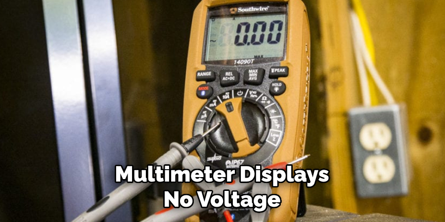
If the multimeter displays no voltage or a significantly erratic or incorrect reading, it suggests a potential issue with the ABS sensor. This could indicate that the sensor is faulty and may require replacement to ensure the effective operation of the ABS system.
This step-by-step testing process is critical for diagnosing issues with the ABS sensor signal. By systematically disconnecting the sensor, setting the multimeter to the correct mode, and observing voltage readings while rotating the wheel hub, technicians can accurately identify problems and ensure the vehicle’s ABS system functions safely and efficiently.
Interpreting Test Results
A. Analyzing Multimeter Readings for Consistency and Variation
Once the multimeter readings are obtained, the immediate step involves analyzing these readings for consistency and variation. Consistent readings across different wheel speeds indicate a healthy ABS sensor, showing the sensor’s ability to accurately track wheel speed changes.
In contrast, significant variations or erratic readings during a stable speed rotation can hint at potential issues within the sensor or its connections. It’s vital to document these readings carefully, noting any fluctuations or instances where they do not align with expected values based on wheel speed.
B. Comparing Readings Across Multiple Wheels
To ensure the ABS system’s overall health, compare the readings obtained from one wheel’s sensor across all wheels on the vehicle. This comparison helps identify discrepancies or anomalies in one or more sensors’ performance.
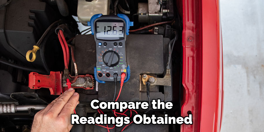
A sensor producing significantly different readings than others might malfunction or suffer from connection issues. Cross-referencing these readings with the manufacturer’s specified ranges is crucial for a comprehensive assessment. Any outlier warrants further investigation, possibly indicating a problem that could affect the ABS system’s functionality.
C. Identifying Abnormal Readings as Potential Sensor Issues
Abnormal readings can manifest in various forms, from a complete lack of output to erratic or unstable readings that do not correlate with wheel speed changes. Identifying these readings as potential sensor issues is a critical diagnostic step. It’s essential to consider that while a faulty sensor is a common culprit, wiring or connector problems can also cause abnormal readings.
Hence, before concluding that a sensor needs replacement, verify the integrity of the related wiring and connectors as previously outlined. Should the sensor itself be at fault, replacement is advisable to restore the ABS system’s proper operation and ensure vehicle safety.
Conducting Dynamic Testing (if applicable)
Dynamic testing under real-world conditions can offer additional insights into the ABS system’s functionality. This stage involves a road test designed to actively engage the ABS system under controlled conditions, ensuring its proper operation throughout various driving scenarios.
A. Performing Road Test to Activate ABS System
Begin with a pre-planned route that includes a variety of surfaces and conditions conducive to safely testing the ABS system. This could involve driving on wet or slippery roads where the ABS is more likely to activate during braking.
Ensure the vehicle is in a safe area, free from traffic and pedestrians, to minimize risk. The goal is to simulate scenarios where the ABS would naturally engage, allowing for observation of its performance in real-time.
B. Observing Vehicle Behavior During Braking Maneuvers
While conducting the road test, pay close attention to the vehicle’s behavior during braking maneuvers, especially under conditions that are likely to trigger the ABS system.
Note the responsiveness of the brakes, any pulsation felt through the brake pedal, and the vehicle’s ability to maintain directional control while braking. These observations can provide valuable feedback on the ABS system’s effectiveness and any potential operation issues.
C. Noting Any ABS Warning Lights or Anomalies
Throughout the test, monitor the dashboard for any ABS warning lights or messages that may indicate a malfunction. Listen for unusual sounds or vibrations that could suggest problems with the ABS components.
Any warning lights, sounds, or handling anomalies should be documented in detail, as they could point to specific issues requiring further investigation or immediate repair.
Conducting dynamic testing by performing a road test, observing vehicle behavior, and noting any unusual signs provides a comprehensive evaluation of the ABS system’s condition. This approach, combined with the static tests previously described, forms a thorough diagnostic process to ensure the ABS system functions safely and as intended.
Documenting Test Results
The efficacy of the ABS diagnostic process largely hinges on meticulous documentation of the test results. This documentation is vital for current diagnostic and repair processes and a valuable reference for future maintenance and troubleshooting.
A. Recording Multimeter Readings and Observations
Each multimeter reading, taken during the static testing phase, should be accurately recorded. This includes noting the specific conditions under which each reading was obtained, such as the wheel’s rotation speed or any variations in the testing environment.
Additionally, observations related to the sensor’s performance, including consistency and any anomalies in the readings, must be meticulously documented. This step ensures that the data is reliable for analyzing the ABS sensor’s health and functionality.
B. Documenting Any Issues Detected During Testing
Issues detected during both static and dynamic testing phases—including abnormal readings, discrepancies in sensor performance between wheels, and any anomalies experienced during the road test—should be clearly documented.
This involves detailing the nature of the issue, its potential impact on the ABS system’s operation, and any immediate corrective actions taken or recommended. Highlighting these issues is crucial for pinpointing areas that require further investigation or immediate intervention to maintain vehicle safety.
C. Providing Detailed Notes for Future Reference
Finally, compiling detailed notes on the testing procedure, findings, and any corrective actions undertaken is essential. These notes should include any deviations from standard testing protocols, reasons for such deviations, and the outcomes of any additional tests performed.
Providing context for the observations and actions will help in future diagnostics, making it easier to understand the ABS system’s historical performance and track any recurring issues or long-term trends. This comprehensive documentation is a knowledge repository, facilitating efficient and informed decision-making in future maintenance and repair scenarios.
Conclusion
The ABS sensor testing process encompasses several detailed steps, from initial inspection and static testing to more dynamic, real-world condition tests. Beginning with a thorough examination of the sensor and its connections, the procedure moves on to static testing using a multimeter to gauge the sensor’s output and integrity.
Dynamic testing, involving a road test, further assesses the system’s performance under conditions likely to activate the ABS. Each phase is critical for identifying issues accurately and ensuring the ABS system’s efficacy and safety.
Regular maintenance of the ABS system is paramount for vehicle safety. The ABS plays a crucial role in maintaining control during emergency braking scenarios, preventing wheel lockup, and enhancing steering control.
Neglecting periodic checks and maintenance can lead to system failure, putting vehicle occupants and other road users at risk. Regular upkeep also extends the lifespan of the ABS components, reducing the likelihood of costly repairs and replacements.
Understanding how to test a ABS sensor with precision is fundamental for successful ABS sensor testing. Always consult the vehicle’s service manual for specific guidance and specifications. Use quality tools and equipment to ensure accurate measurements.
Pay close attention to the condition of wiring and connectors, as these can often be the culprits of ABS issues. Document testing phases meticulously for future reference. Lastly, don’t rush the process—taking the time to thoroughly test and diagnose can prevent misdiagnosis and ensure the ABS system functions reliably and effectively.
About
Safety Fic is a distinguished figure in the world of Diy design, with a decade of expertise creating innovative and sustainable Diy solutions. His professional focus lies in merging traditional craftsmanship with modern manufacturing techniques, fostering designs that are both practical and environmentally conscious. As the author of diy, Safety Fic delves into the art and science of Safety Fic-making, inspiring artisans and industry professionals alike.
Education RMIT University
(Melbourne, Australia) Associate Degree in Design (Safety Fic) Focus on sustainable design, industry-driven projects, and practical craftsmanship. Gained hands-on experience with traditional and digital manufacturing tools, such as CAD and CNC software.
Nottingham Trent University
(United Kingdom) Bachelor’s in diyfastly.com and Product Design (Honors) Specialized in product design with a focus on blending creativity with production techniques. Participated in industry projects, working with companies like John Lewis and Vitsoe to gain real-world insights.
Publications and Impact
In diy, Safety Fic his insights on indoor design processes, materials, and strategies for efficient production. His writing bridges the gap between artisan knowledge and modern industry needs, making it a must-read for both budding designers and seasoned professionals.