

Modern vehicles rely heavily on oxygen (O2) sensors to monitor and regulate the air-fuel ratio for efficient combustion. These sensors play a crucial role in reducing harmful emissions, improving fuel economy, and maintaining engine performance. However, when an O2 sensor fails or is removed, it can trigger a “Check Engine” light and cause the car’s computer to operate inefficiently.
An O2 sensor simulator acts as a small electronic circuit that mimics the signal of a functioning oxygen sensor, tricking the engine control unit (ECU) into thinking that everything is working correctly. Building your own O2 sensor simulator can be a cost-effective solution for testing or off-road tuning applications.
However, it must be done carefully and responsibly, as tampering with emissions systems for street vehicles is illegal in many regions. In this guide on how to make O2 sensor simulator, we will discuss the basic principles and steps involved in creating a functional O2 sensor simulator.
Tools and Materials You’ll Need
- Soldering Iron and Solder Wire
- Heat-shrink Tubing and Electrical Tape
- Resistors (Values Such as 1kω, 10kω, and 100kω)
- Capacitors (Usually 1µf to 10µf)
- A Small Breadboard or Prototyping Board
- A Voltmeter or Multimeter for Testing
- Automotive-grade Wiring and Connectors
- Power Supply (12v DC, Typical Car Voltage)
- Heat-resistant Casing or Small Plastic Box
- Wire Stripper and Pliers
10 Step-By-Step Guidelines on How to Make O2 Sensor Simulator
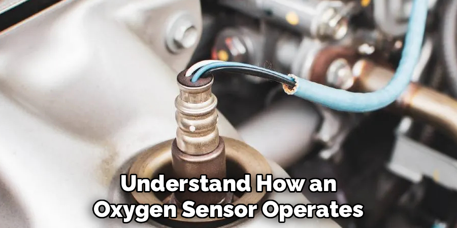
Step 1: Understand the Function of an O2 Sensor
Before starting, it’s important to understand how an oxygen sensor operates. The sensor measures the oxygen content in the exhaust gas and generates a voltage signal (typically between 0.1V and 0.9V) that the ECU reads to determine if the engine is running rich or lean.
By simulating this voltage signal, the ECU can be tricked into thinking the air-fuel mixture is ideal. This concept forms the foundation of your simulator. Understanding the waveform pattern, switching speed, and signal range will help you create an accurate device that mimics a real sensor’s behavior.
Step 2: Identify the Sensor Type and Signal Requirements
Oxygen sensors come in two primary types: narrowband and wideband. Narrowband sensors output a simple oscillating voltage signal, while wideband sensors use more complex current-based feedback systems.
For DIY simulators, narrowband sensors are easier to replicate because they use a basic 0.1–0.9V signal. Use your vehicle’s repair manual or an online resource to identify which type your car uses. If it’s narrowband, you can proceed with a resistor-capacitor-based circuit design. Wideband systems are more complicated and generally not recommended for beginners.
Step 3: Design the Circuit Schematic
The simplest O2 sensor simulator can be built using resistors and capacitors that create a fluctuating voltage signal between 0.1V and 0.9V. Draw a schematic before you start soldering. Typically, you’ll connect resistors in series with the capacitor to create a waveform that slowly switches between low and high voltages.
Add a voltage divider network using resistors to fine-tune the signal output. You can also incorporate a small operational amplifier (op-amp) if you want a more dynamic signal. Once your schematic is complete, double-check the values using an online O2 simulator circuit reference or an electronics calculator.
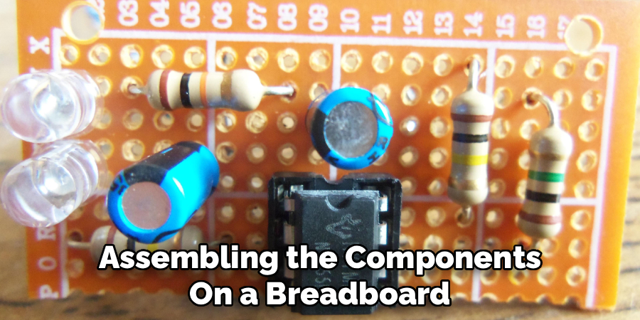
Step 4: Assemble the Components on a Breadboard
Start assembling the components on a breadboard for easy testing and modification. Place the resistors and capacitors according to your schematic and connect them to the power supply. Ensure proper polarity for capacitors and consistent wire color coding for positive and ground connections.
After placing the components, use your multimeter to verify voltage levels across each node. This step ensures your design works before final soldering. A breadboard setup allows you to tweak resistor values to achieve a more realistic O2 signal output that matches your vehicle’s sensor profile.
Step 5: Test the Output Voltage Signal
Once the breadboard circuit is ready, connect the voltmeter to the output terminal to check the voltage fluctuation. Ideally, it should oscillate between approximately 0.1V and 0.9V at a steady pace. You can also test it by connecting it to a digital oscilloscope for a more detailed waveform view.
If the voltage is too low or too high, adjust the resistor or capacitor values until it stabilizes within the correct range. Remember, the goal is to produce a realistic switching pattern that the ECU interprets as a normal sensor output.
Step 6: Solder the Circuit on a Prototyping Board
After successful testing, transfer the circuit from the breadboard to a permanent prototyping board. Use a fine-tipped soldering iron to carefully solder each connection. Ensure that solder joints are smooth, shiny, and free from short circuits.
Once all components are in place, trim excess leads and use heat-shrink tubing to insulate exposed wires. This makes the circuit durable and safe for use in the vehicle’s engine bay, where heat and vibration are common.
Step 7: Encapsulate the Circuit in a Protective Housing
To protect your O2 sensor simulator from heat, moisture, and vibration, enclose it in a heat-resistant plastic box or casing. Drill small holes for wire outlets and seal the edges using high-temperature silicone or epoxy.
Ensure that the housing is compact enough to fit near the sensor connector but not too close to hot exhaust components. A neat, well-insulated housing will enhance longevity and safety.
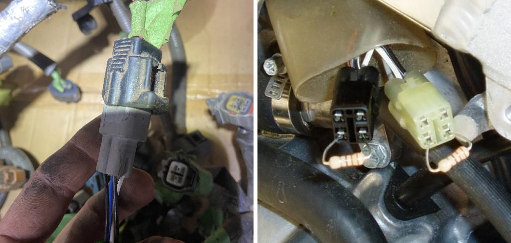
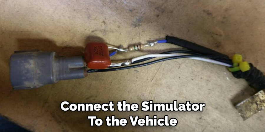
Step 8: Connect the Simulator to the Vehicle
Locate the O2 sensor connector under your vehicle or near the catalytic converter. Disconnect the faulty sensor and plug your simulator into the harness using compatible connectors. Make sure to match the power, ground, and signal wires correctly according to the wiring diagram.
Once connected, secure the wires using zip ties or electrical tape. Turn on the ignition without starting the engine to see if the “Check Engine” light remains off. If it does, your simulator is successfully transmitting a believable signal to the ECU.
Step 9: Fine-Tune and Monitor Performance
Start the engine and let it idle. Use a diagnostic scanner to monitor the O2 sensor voltage reading. It should fluctuate as if a normal sensor were functioning. If the reading is too stable or erratic, you may need to tweak the resistor or capacitor values slightly.
Drive the car for a short distance while keeping an eye on fuel economy and engine response. The goal is to achieve smooth operation without triggering any fault codes. Fine-tuning may take several attempts, so patience is key.
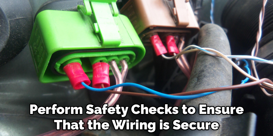
Step 10: Conduct Safety Checks and Finalize Installation
Before finalizing the installation, perform safety checks to ensure that the wiring is secure and away from moving parts or hot surfaces. Wrap the circuit and connectors with additional insulation if necessary.
Finally, clear any stored fault codes using an OBD2 scanner and observe for several days to ensure the system remains stable. Once confirmed, you’ve successfully built and installed a working O2 sensor simulator for testing or research purposes.
Following these steps on how to make O2 sensor simulator can save you time and money from having to constantly replace faulty sensors for testing or research purposes. Additionally, this DIY project allows you to have more control over the performance of your vehicle’s oxygen sensor system.
Additional Tips
- Always use automotive-grade components that can withstand high temperatures.
- Keep your design simple if it’s your first attempt; advanced microcontroller-based simulators can come later.
- Avoid routing wires near the exhaust manifold or engine fan to prevent heat damage.
- Use a heat-shrink sleeve instead of regular tape for long-term durability.
- If your ECU keeps showing error codes, verify the grounding and voltage output with a multimeter before redoing the circuit.
- Consider using a pre-made circuit board template from automotive electronics forums for better precision.
Common Mistakes to Avoid
- Using low-quality resistors that drift in value under heat.
- Forgetting to check the polarity of capacitors can damage the circuit.
- Poor soldering that leads to short circuits or intermittent signals.
- Placing the simulator too close to the hot engine parts.
- Ignoring the legal implications of using simulators on road-registered vehicles.
Do You Need to Use Professionals?
In most cases, a basic O2 simulator can be built by anyone with moderate electronics experience. However, if you’re not confident in reading wiring diagrams, soldering, or testing circuits, it’s safer to seek help from a professional auto electrician or technician.
Professionals can ensure your connections are secure, the voltage signal is accurate, and your ECU isn’t at risk of damage. Additionally, they can test your circuit with advanced diagnostic equipment to confirm performance. Remember that professional installation may cost extra, but it can save you from costly ECU or wiring damage caused by incorrect DIY work.
How Much Will It Cost?
The cost of building an O2 sensor simulator largely depends on the materials and complexity of the design. A basic resistor-capacitor simulator may cost around $5–$10 if you already have tools like a soldering iron and a multimeter.
If you include additional features such as an op-amp or protective enclosure, the total may rise to $20–$30. Professional installation or testing can add another $30–$50, depending on your area. Even with these costs, it’s still significantly cheaper than replacing an entire O2 sensor, which can cost $80–$250 depending on the vehicle model.
Frequently Asked Questions
Q1: Can an O2 Sensor Simulator Improve Fuel Economy?
A1: While an O2 sensor simulator can trick the ECU into maintaining a balanced air-fuel ratio, it doesn’t inherently improve fuel economy. Its main function is to mimic sensor output for testing or off-road use.
Poor tuning or improper voltage settings can actually reduce efficiency. Always test carefully to avoid engine performance issues.
Q2: Is It Legal to Use an O2 Sensor Simulator on the Road?
A2: In many regions, it’s illegal to tamper with emission control systems for vehicles driven on public roads. O2 sensor simulators are typically used for off-road, racing, or testing applications. Always check local emission laws before installing one in a road-registered vehicle.
Q3: Can I Use the Simulator Permanently?
A3: O2 sensor simulators are best used temporarily for troubleshooting or diagnostic purposes. Permanent use may lead to long-term engine management issues and legal complications. For daily driving, it’s recommended to replace the faulty sensor with a genuine OEM part.
Conclusion
Building an O2 sensor simulator can be an educational and cost-saving project for automotive enthusiasts. It teaches fundamental circuit design, signal simulation, and diagnostic skills that can be applied to many other automotive systems. However, it’s vital to use this tool responsibly and within legal boundaries.
By carefully following each step on how to make O2 sensor simulator—designing, assembling, testing, and installing—you can create a functional O2 simulator that helps in diagnosing or experimenting with vehicle tuning. Just remember: while DIY solutions can be effective, safety, legality, and environmental responsibility should always come first.
About
Safety Fic is a distinguished figure in the world of Diy design, with a decade of expertise creating innovative and sustainable Diy solutions. His professional focus lies in merging traditional craftsmanship with modern manufacturing techniques, fostering designs that are both practical and environmentally conscious. As the author of diy, Safety Fic delves into the art and science of Safety Fic-making, inspiring artisans and industry professionals alike.
Education RMIT University
(Melbourne, Australia) Associate Degree in Design (Safety Fic) Focus on sustainable design, industry-driven projects, and practical craftsmanship. Gained hands-on experience with traditional and digital manufacturing tools, such as CAD and CNC software.
Nottingham Trent University
(United Kingdom) Bachelor’s in diyfastly.com and Product Design (Honors) Specialized in product design with a focus on blending creativity with production techniques. Participated in industry projects, working with companies like John Lewis and Vitsoe to gain real-world insights.
Publications and Impact
In diy, Safety Fic his insights on indoor design processes, materials, and strategies for efficient production. His writing bridges the gap between artisan knowledge and modern industry needs, making it a must-read for both budding designers and seasoned professionals.