

Are you experiencing problems with your 3-wire cam sensor? Is it not functioning properly or giving inconsistent readings?
How to test a 3 wire cam sensor is an essential diagnostic procedure to ensure the proper functioning of an engine’s timing system. This sensor plays a critical role in monitoring the position of the camshaft and relaying this information to the engine control unit (ECU) for precise ignition and fuel injection timing. When a cam sensor malfunctions, it can lead to engine performance issues, including rough idling, misfires, or even a no-start condition.

By following a systematic testing approach, you can determine whether the sensor is operating correctly or requires replacement, saving time and cost for further diagnosis or repairs. Let’s take a closer look at how to test a camshaft sensor.
What Are the Benefits of Testing a Camshaft Sensor?
Testing a camshaft sensor can have several benefits, including:
- Improved Engine Performance: If the sensor is not functioning correctly, it can cause issues with fuel and ignition timing, resulting in reduced engine power and efficiency. You can restore your engine’s performance by testing and replacing a faulty sensor.
- Cost Savings: By identifying and replacing a malfunctioning camshaft sensor early on, you can prevent further damage to other components that may occur if the issue is left untreated. This can help save on costly repairs down the line.
- Preventing Safety Hazards: A failed camshaft sensor can lead to serious safety hazards, such as stalling or an inability to start the engine. By regularly checking and replacing this sensor when necessary, you can ensure your safety and that of others on the road.
- Improved Fuel Efficiency: The camshaft sensor plays a crucial role in determining the fuel-to-air ratio in your engine. If it is not functioning correctly, it can result in decreased fuel efficiency and higher gas consumption.
What Will You Need?
To replace a camshaft sensor, you will need:
- A new camshaft sensor specific to your vehicle’s make and model
- Replacement gaskets (if necessary)
- Socket wrench set
- Screwdrivers (Phillips and flathead)
- Pliers
- Rags or paper towels
Once you have gathered all the necessary materials, you can begin replacing your camshaft sensor.
8 Easy Steps on How to Test a 3 Wire Cam Sensor
Step 1: Identifying the Issue
Before testing your 3-wire camshaft sensor, it’s crucial to determine whether it is the source of the problem. Common symptoms of a faulty camshaft sensor include difficulty starting the engine, erratic idle, reduced fuel efficiency, stalling, or decreased overall performance.
Additionally, your vehicle’s check engine light may illuminate, indicating a possible issue with the camshaft sensor. Using an OBD2 scanner, you can retrieve diagnostic trouble codes (DTCs) to confirm if the sensor is malfunctioning. If the codes suggest a camshaft sensor issue, you can proceed with testing to verify its condition before considering replacement.
Step 2: Verifying Connections
Before jumping to conclusions about the camshaft sensor’s failure, it is essential to inspect its electrical connections. Begin by locating the camshaft position sensor, which is generally found near the engine’s camshaft or timing cover. Check for any loose, corroded, or damaged wiring and connectors that might be causing an intermittent or complete signal loss.
Carefully unplug the sensor’s connector and inspect the pins for bends, corrosion, or debris. Use electrical contact cleaner if necessary to clean the connector thoroughly. Securely reconnect the harness to ensure a tight fit, as a loose connection can mimic sensor failure symptoms. Once you’ve verified that all connections are in proper condition, test the sensor to rule out further issues.
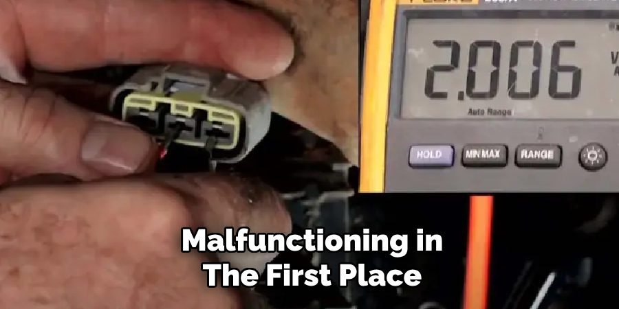
Step 3: Testing the Sensor
To test the sensor, you will need a multimeter or diagnostic tool appropriate for the type of sensor you are working with. Begin by consulting the vehicle’s service manual to locate the specifications for the sensor, including the expected voltage, resistance, or signal output ranges.
Set your multimeter to the correct mode—voltage, resistance, or continuity—depending on the sensor type. Carefully connect the multimeter probes to the sensor’s terminals or back-probe the sensor wiring harness, ensuring you do not damage the connectors. If you are using a diagnostic tool, connect it to the vehicle’s onboard diagnostic port to monitor live data from the sensor.
While testing, compare the results to the manufacturer’s specifications. A reading outside the specified range may indicate a malfunctioning sensor. For sensors with dynamic outputs, such as oxygen or speed sensors, observe the sensor’s behavior under varying conditions (e.g., different engine speeds) to verify proper functionality.
If the sensor produces no signal or provides erratic output, it is likely defective and may need replacement. Ensure all testing is conducted in a safe environment, following proper safety precautions, especially if the engine needs to be running for dynamic testing.
Step 4: Consulting Technical Resources
Consulting technical resources is a critical step in diagnosing and repairing complex systems. These resources may include service manuals, manufacturer guidelines, wiring diagrams, or diagnostic flowcharts. Service manuals often provide detailed troubleshooting procedures, technical specifications, and step-by-step instructions tailored to specific systems or components.
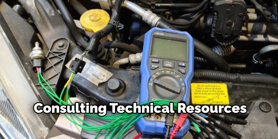
Manufacturer guidelines can offer insights on everyday issues, recommended testing tools, and precision repair methodologies. Wiring diagrams are essential for identifying electrical circuits and connections, helping to trace faults or malfunctions efficiently. Additionally, diagnostic flowcharts are a systematic tool to narrow down potential problems based on observable symptoms. Whenever consulting these resources, ensure they are current and applicable to the specific make, model, or system you are working on, as even minor model variations can impact compatibility and repair techniques.
Step 5: Seeking Expert Assistance
If troubleshooting efforts and diagnostic tools do not yield a solution, seeking expert assistance can save time and prevent further complications. Professional technicians have specialized knowledge and access to advanced diagnostic equipment that may not be available to the average user. When reaching out to an expert, provide a detailed account of the issue, including any error codes, symptoms observed, and steps already taken during the troubleshooting process.
This information can help streamline the diagnosis and resolution process. Additionally, verify the expertise of the technician by ensuring they are certified and experienced in handling your specific system or equipment. Collaborating with an expert can often uncover complex issues that require in-depth understanding and provide a safe and effective repair.
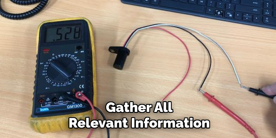
Step 6: Gather All Relevant Information
Begin by compiling all necessary details about the issue. Document the exact symptoms, error messages, and the circumstances under which the problem occurs. Include any recent changes to the system or environment that might have contributed to the issue. This comprehensive record will serve as a crucial reference for the technician, helping to identify the root cause efficiently.
Step 7: Perform a Preliminary Diagnosis
With the gathered information, conduct a preliminary diagnosis to narrow down potential causes. Analyze the documented symptoms and error messages, cross-referencing them with known issues or troubleshooting guides. Use diagnostic tools, if available, to test the system components or configurations. This step helps isolate the problem and develop a more focused approach to the repair process.
Step 8: Implement a Solution
Once the root cause has been identified, an appropriate solution can be found. This may involve replacing faulty components, updating software, modifying configurations, or applying patches. Ensure any changes are made methodically and carefully to avoid introducing new issues. Document each action taken to maintain a clear record of the troubleshooting process.
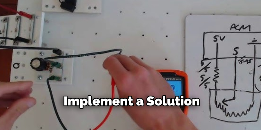
By following a structured approach and carefully implementing the solution, you can prevent future occurrences of the same issue and improve the system’s overall functioning.
5 Things You Should Avoid
- Skipping a Visual Inspection: Never overlook a thorough visual inspection of the wiring harness and connectors. Damaged wires or corroded connectors can cause inaccurate readings or sensor malfunctions.
- Using Improper Testing Equipment: Avoid using tools not designed for automotive diagnostics, such as mismatched multimeters or probes, as these can damage the sensor or yield unreliable results.
- Testing Without Reference Information: Do not test the cam sensor without consulting the vehicle’s service manual. Lacking reference voltage or wiring diagram specifics increases the risk of misdiagnosis or incorrect testing.
- Applying Excessive Force: Never apply unnecessary pressure to the sensor or its connection points. Mishandling can lead to physical damage, making the sensor inoperable.
- Ignoring Safety Precautions: Always disconnect the battery before testing to prevent short circuits. Ignoring basic safety protocols can result in personal injury or further damage to the system.
By avoiding these common mistakes, technicians can ensure the accurate diagnosis and testing of sensors.
Conclusion
Testing a 3-wire cam sensor requires a methodical approach to ensure accurate results and avoid potential damage.
By thoroughly understanding the wiring system, using the correct tools such as a multimeter, and adhering to safety precautions, technicians can effectively diagnose the condition of the sensor. Following manufacturer guidelines and testing procedures is crucial to achieve reliable outcomes. With proper handling and careful execution, testing a 3-wire cam sensor becomes a straightforward and efficient process, supporting the overall functionality of the engine system.
Hopefully, the article on how to test a 3 wire cam sensor has provided you with valuable information and insights on the importance of cam sensors in engine systems.