

The crankshaft position sensor is a crucial component in modern engines, responsible for monitoring the position and rotational speed of the crankshaft. This information is sent to the engine control unit (ECU) to regulate critical engine functions such as ignition timing and fuel injection. A faulty crankshaft position sensor can lead to engine performance issues, including stalling, misfiring, or failure to start. Testing the sensor is an essential diagnostic step to ensure proper engine operation and identify potential problems early. In this blog post, we’ll walk you through the steps on how to test crankshaft position sensor so that you can get back to using it in no time! So grab your tools, and let’s get started!
What Is a Crankshaft Position Sensor?
A crankshaft position sensor is a crucial component in an internal combustion engine. Its primary purpose is to monitor the position and rotational speed of the crankshaft, providing real-time data to the engine control unit (ECU). This information is vital for the precise control of engine functions such as fuel injection, ignition timing, and variable valve timing. The crankshaft position sensor ensures that these processes are synchronized, which is essential for optimizing engine performance, fuel efficiency, and emissions control. These sensors can be found in different forms, such as magnetic or Hall-effect sensors, depending on the specific design of the engine.
Symptoms of a Faulty Crankshaft Position Sensor
A malfunctioning crankshaft position sensor can lead to a variety of performance issues in a vehicle. One common symptom is difficulty starting the engine or the engine failing to start at all, as the sensor’s data is critical for proper ignition timing. Another indication is engine misfires or rough idling, caused by incorrect or irregular signals sent to the ECU. Drivers may also notice reduced fuel efficiency and sluggish acceleration, as the engine’s performance is compromised without accurate timing information. Furthermore, a faulty sensor often triggers the check engine light on the dashboard. If any of these symptoms occur, it is important to have the sensor inspected and repaired promptly to avoid further damage to the engine.
10 Methods How to Test Crankshaft Position Sensor
1. Use a Digital Multimeter to Check Resistance
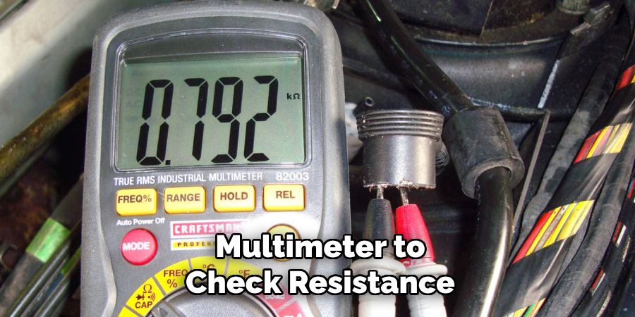
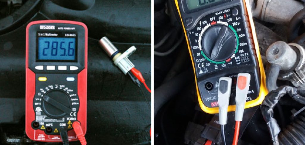
One of the most basic and effective ways to test a crankshaft position sensor is with a digital multimeter set to measure resistance (ohms). Begin by disconnecting the sensor from the wiring harness to isolate it from the vehicle’s electronics. Touch the multimeter probes to the sensor’s terminals—typically two or three pins depending on the sensor type. Compare the resistance reading with the manufacturer’s specified range, which you can usually find in a repair manual or online. A sensor that reads infinite resistance (open circuit) or zero (short circuit) is most likely faulty and should be replaced.
2. Perform an Output Voltage Test While Cranking
For sensors that operate using magnetic induction, you can test the output voltage during engine cranking. Set your multimeter to AC voltage and connect the probes to the sensor’s terminals while the harness is plugged in or using back-probing techniques. Have a helper crank the engine while you observe the meter. A healthy crankshaft sensor should produce a small but consistent voltage signal—often between 0.5 and 1.5 volts AC. If there’s no voltage or it fluctuates wildly, the sensor could be failing or improperly positioned.
3. Use a Scan Tool to Monitor Live Data
Advanced diagnostic tools with live data capabilities allow you to observe the crankshaft position sensor’s output in real time. Connect the scanner to your vehicle’s OBD-II port and navigate to engine or powertrain parameters. You should find a readout for crankshaft position (CKP) signal. When the engine is cranking or running, this data should show steady and consistent values. Erratic or missing readings could indicate a failing sensor, damaged wiring, or issues with the sensor’s alignment with the reluctor ring.
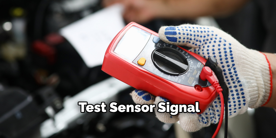
4. Test Sensor Signal with an Oscilloscope
For those who have access to an automotive oscilloscope, testing the crankshaft sensor signal with this tool offers the most detailed insight. Connect the oscilloscope leads to the sensor wires and crank the engine. The screen should display a waveform pattern that corresponds to the crankshaft’s rotation. A healthy signal will show a smooth and repeating waveform with regular peaks. Distorted or inconsistent waveforms often point to a defective sensor, interference, or a damaged tone ring.
5. Inspect for Physical Damage and Debris
Before diving deep into electrical testing, it’s wise to visually inspect the sensor for signs of damage. Remove the sensor from the engine and examine it for metal shavings, cracks, melted plastic, or heavy oil contamination. Metal debris, in particular, can interfere with magnetic sensors, leading to poor or erratic signal transmission. Cleaning the sensor or the mounting area may resolve the issue, but if physical wear is present, replacement is generally necessary.
6. Check for Proper Sensor Gap
The crankshaft sensor must be properly aligned with the crankshaft’s reluctor ring or tone wheel. Using feeler gauges, check the air gap between the sensor tip and the rotating ring. Consult your vehicle’s repair manual for the exact specification—usually between 0.020″ and 0.060″. If the gap is too wide or the sensor is not flush, the sensor may not pick up the crankshaft’s movement accurately. Improper spacing could be the result of a poorly installed sensor, warped mounting surface, or engine wear.
7. Examine the Sensor Wiring and Connectors
Faulty wiring can mimic the symptoms of a bad crankshaft sensor. Carefully inspect the sensor’s wiring harness, looking for frayed wires, brittle insulation, corrosion, or loose connections. Pay special attention to areas where the harness bends or passes near hot engine parts. Wiggle the wires while monitoring the sensor’s output voltage to detect any intermittent issues. Repair or replace damaged wiring and connectors to restore proper sensor communication.
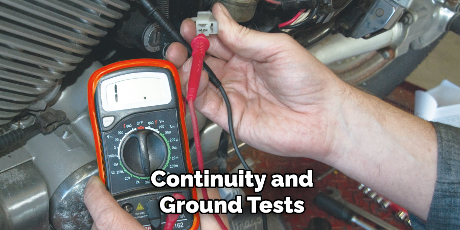
8. Perform Continuity and Ground Tests
Continuity and proper grounding are essential for sensor function. With the ignition off, use your multimeter in continuity mode to verify that the ground wire for the sensor is properly connected to the engine ground. You should hear a beep or see near-zero resistance if the ground is intact. Also, test continuity from the sensor’s terminals to the corresponding ECU terminals to ensure the signal path is unbroken. Faulty grounds or open signal paths can cause intermittent stalling, rough idling, or no-start conditions.
9. Observe Engine Behavior During Cold Start
A practical, though less technical, way to test a crankshaft sensor is by observing the engine’s behavior during a cold start. A failing sensor may work intermittently, especially as it heats up. If the engine has trouble starting when cold, stalls shortly after starting, or misfires until the engine warms up, the crankshaft sensor could be deteriorating. While not a definitive test, this observational method often provides clues that a more detailed diagnosis should follow.
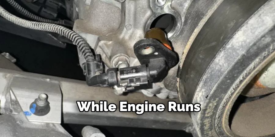
10. Use the “Wiggle Test” While Engine Runs
For sensors that are suspected of having loose wiring or intermittent failures, a wiggle test is useful. With the engine idling and the sensor connected, gently move the wiring harness and sensor connector. If the engine stumbles, hesitates, or shuts off, it suggests a loose connection or damaged wire. This test can confirm whether the fault lies in the sensor itself or in the supporting harness and connectors.
Maintenance and Upkeep
Regular maintenance and proper care of the vehicle’s sensors and wiring can prevent many diagnostic challenges. Inspect wiring harnesses and connectors periodically for signs of wear, corrosion, or damage. Clean connectors with appropriate electrical contact cleaners to ensure a strong and stable connection. Additionally, avoid excessive moisture or exposure to harsh chemicals in the engine bay, as these can degrade the insulation on wires over time. Replacing worn-out components promptly and following the manufacturer’s maintenance schedule will help ensure the longevity and proper function of the vehicle’s electrical systems.
Safety Considerations
When working on a vehicle’s electrical systems, safety should always be a top priority. Begin by disconnecting the battery to prevent accidental shocks or short circuits. Use insulated tools and avoid wearing metal accessories like watches or bracelets while handling electrical components. Always refer to the vehicle’s manual for specific instructions and adhere to proper safety protocols. If you encounter high-voltage systems, such as those in hybrid or electric vehicles, exercise extreme caution as these can pose significant risks. It is advisable to wear protective gloves and goggles while performing maintenance, and if unsure, consult a qualified professional to avoid potential hazards.
Conclusion
Testing a crankshaft position sensor may seem daunting, but with the right tools and step-by-step methods, it becomes manageable. From simple multimeter resistance checks to advanced waveform analysis with an oscilloscope, these methods provide both beginner and advanced DIYers with a path to diagnose sensor health accurately. Always remember to cross-check your findings with your vehicle’s specific repair manual for proper specifications and procedures. Thanks for reading our blog post on how to test crankshaft position sensor! We hope you found it helpful and informative.
About
Safety Fic is a distinguished figure in the world of Diy design, with a decade of expertise creating innovative and sustainable Diy solutions. His professional focus lies in merging traditional craftsmanship with modern manufacturing techniques, fostering designs that are both practical and environmentally conscious. As the author of diy, Safety Fic delves into the art and science of Safety Fic-making, inspiring artisans and industry professionals alike.
Education RMIT University
(Melbourne, Australia) Associate Degree in Design (Safety Fic) Focus on sustainable design, industry-driven projects, and practical craftsmanship. Gained hands-on experience with traditional and digital manufacturing tools, such as CAD and CNC software.
Nottingham Trent University
(United Kingdom) Bachelor’s in diyfastly.com and Product Design (Honors) Specialized in product design with a focus on blending creativity with production techniques. Participated in industry projects, working with companies like John Lewis and Vitsoe to gain real-world insights.
Publications and Impact
In diy, Safety Fic his insights on indoor design processes, materials, and strategies for efficient production. His writing bridges the gap between artisan knowledge and modern industry needs, making it a must-read for both budding designers and seasoned professionals.